
LED Polarity Identification Guide: How to Determine Anode vs Cathode Using Lead Length and Flat Edge Markings
Have you ever spent three hours troubleshooting a custom circuit board, questioning every single solder joint and life choice, only to realize you installed a tiny light-emitting diode backward? Trust me, I've been there. It's a classic rite of passage for anyone working with electronics, from weekend hobbyists to seasoned hardware engineers. Understanding LED polarity identification is one of those basic skills that saves you endless headaches, burnt components, and ruined project timelines.
Look, LEDs aren't like standard incandescent bulbs. You can't just hook them up any which way and expect magic to happen. They're semiconductors. That means electric current flows in exactly one direction, and if you flip the connections, your project stays completely dark. Or worse, you accidentally fry the component by exceeding its reverse breakdown voltage.
In this comprehensive guide, we're going to break down the physical cues built right into standard components. We'll focus heavily on using lead length and the flat edge marking to spot your positive and negative terminals instantly. By the end of this read, you'll spot the difference in half a second flat.
So grab your magnifying glass and let's dive straight into the physical anatomy of these frustratingly small components.
Decoding Physical Cues: Pinpointing Lead Length and Flat Edge Markings
When you pull a brand-new component out of the ESD bag, the manufacturer has already given you visual cheat codes. You don't need fancy test equipment just yet. All you need is decent lighting and basic visual inspection techniques to master LED polarity identification.
The two most reliable physical indicators on through-hole components are the asymmetrical metal legs and the subtle notch on the plastic epoxy body. Manufacturers standardized these features decades ago so assembly line workers and automated equipment could quickly determine anode vs cathode orientation without guessing.
However, relying solely on eye inspection requires knowing exactly what you're looking at. Cut legs, re-used parts, or non-standard manufacturing can sometimes trip you up. Let's break down how to read these physical markers accurately every single time.
Honestly? Once you get the hang of these two markers, you'll rarely need to pull out a multimeter for standard through-hole parts.
The Golden Rule of Lead Length
Fresh out of the factory, a standard through-hole light-emitting diode features two flexible metal legs extending from the base. Pay close attention to their height. They aren't identical, and that difference is entirely by design.
The longer leg is always your anode, which connects to the positive side of your power source. The shorter leg represents the cathode, which must connect to the ground or negative side. It's a clean, simple convention: longer equals positive, shorter equals negative.
Here is a quick reference checklist for visual pin inspection:
- Long Lead: Positive connection (Anode). Connects toward your power supply line.
- Short Lead: Negative connection (Cathode). Connects toward ground (GND).
- Trimmed Leads: If both legs are cut to equal length for a circuit board, lead length can no longer be trusted. You must rely on body markings.
Remember this simple memory trick: "You want more (longer) positive things in your life." Works every time.
Spotting the Flat Edge on the Epoxy Lens
What happens when you're working with recycled parts or leads that have already been trimmed down to fit a PCB? That's where the flat edge marking on the outer plastic casing becomes your ultimate backup plan.
If you examine the round plastic dome (the epoxy resin body) from the bottom, you'll notice it isn't a perfect circle. One side features a distinctly shaved, flat lip. This flattened ridge aligns directly with the internal structure of the negative terminal.
The flat edge always points directly to the cathode (negative side). The remaining rounded side corresponds to the anode (positive side). Run your fingernail around the base rim if you can't immediately see it; your nail will catch on the flat section straight away.
Even on tiny 3mm components, that subtle notch is there. You just have to look closely.
Inside the Epoxy Lens: Internal Structure and Advanced Verification
Sometimes the outer case gets scratched up, or maybe you're dealing with a cheap generic component where the flat edge is barely noticeable. Don't panic. We can look straight through the clear plastic body to examine the metal internal framework directly.
Inside the clear epoxy shell, you'll see two distinct metal posts holding the tiny semiconductor die. These internal posts are shaped differently to support the fragile bond wire and provide heat dissipation. Understanding this internal anatomy gives you a third layer of verification for accurate anode vs cathode identification.
Combining visual body checks with basic electrical tests guarantees 100% accuracy every time you build. Let's look at how internal layout and simple tools settle the debate instantly.
Seriously, learning to read internal metal posts is like having X-ray vision for electronics.
Reading the Internal Anvil and Post
Hold your component up to a bright light source. Look closely through the transparent casing at the two metal pieces sitting inside the resin.
You'll notice one large metal block shaped roughly like a flag or a heavy construction anvil, and one significantly smaller, thinner post. The large triangular chunk—the anvil—is connected to the cathode (negative terminal). The small slender post connects to the anode (positive terminal).
Here is how the internal anatomy breaks down step-by-step:
- Hold the component up against a wall light or window.
- Identify the larger metal triangular flag (the anvil). This is your cathode.
- Locate the tiny bond wire extending from the anvil over to the smaller post (the anode).
- Align your PCB layout matching the larger internal block to your ground trace.
While this internal visual check is extremely reliable for clear standard 5mm packages, diffused or colored plastic cases can blur the internal view. In those edge cases, test tools are your best friend.
Verifying Polarity with a Multimeter
When physical inspection leaves any room for doubt, your digital multimeter provides concrete proof. Every modern multimeter includes a dedicated diode testing mode designed specifically for this task.
Turn your multimeter dial to the diode symbol (it looks like an arrow pushing against a vertical line). Plug your red test lead into the positive/voltage jack and your black test lead into the COM (ground) jack. Touch the red probe to one leg and the black probe to the other.
If the component illuminates softly and your meter displays a forward voltage reading (typically between 1.8V and 3.3V depending on color), your red probe is touching the anode and your black probe is touching the cathode. If the screen displays "OL" or no light appears, reverse the probes and try again.
It takes five seconds, eliminates all guesswork, and ensures you won't have to desolder anything later.
Common Questions About LED Polarity Identification
What happens if I connect an LED backward in a circuit?
In most low-voltage DC circuits, connecting the component backward simply prevents current from flowing, meaning it won't light up. However, if the reverse voltage applied exceeds the component's maximum reverse breakdown rating (typically around 5V), the internal semiconductor junction can break down permanently, destroying the device.
Is the flat edge always reliable on every brand?
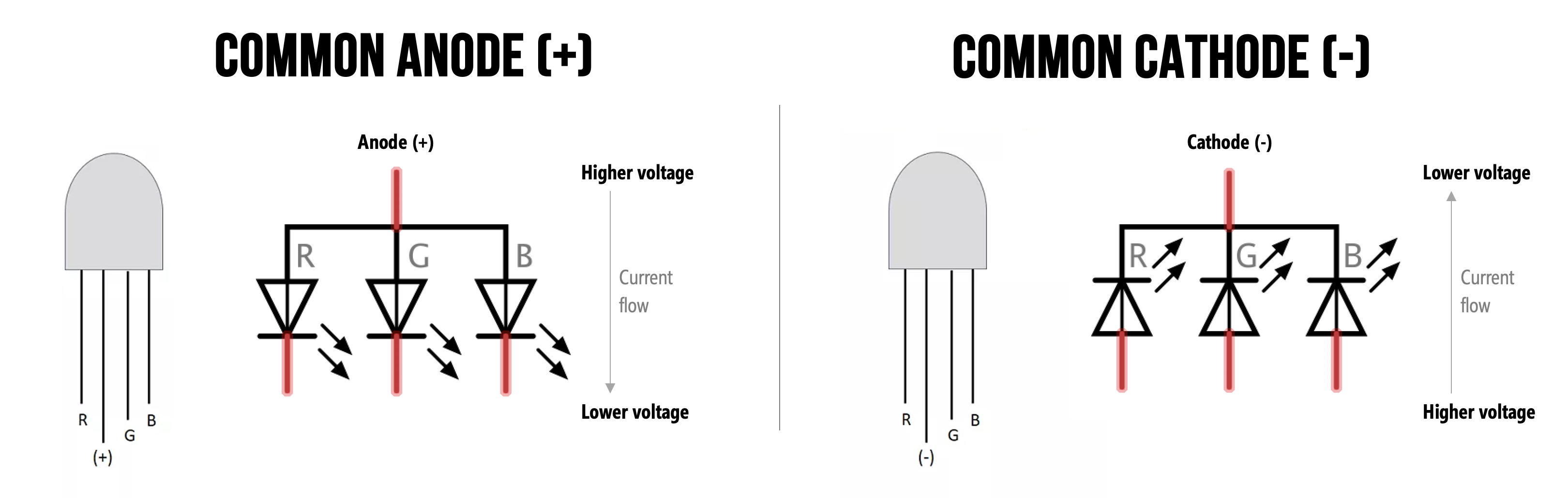
For standard 3mm, 5mm, and 10mm through-hole components, the flat edge marking is a universally recognized standard pointing to the cathode. However, some non-standard, vintage, or specialty RGB components may deviate. Always double-check with a multimeter if you are using unbranded or specialized parts.
How do I determine polarity on Surface Mount (SMD) LEDs?
Surface mount components don't have long wire legs. Instead, look at the bottom or top of the tiny SMD package. Manufacturers place a small colored dot, a printed notch, or a printed "T" shape on the underside. The top line of the "T" or the side with the colored mark almost always designates the cathode terminal.