
Anode Positive or Negative LEDs: Circuit Board Silk Screen and Cathode Notch Identification
Ever soldered an entire batch of custom circuit boards, powered them up with a sense of pride, only to find half your status lights completely dark? If you have been in the electronics game long enough, it happens. We have all been there, staring at a silent board and wondering where it all went wrong. The culprit is almost always a flipped diode. Figuring out whether you are dealing with an anode positive or negative LED setup sounds basic on paper, but out in the wild, micro-packages and cryptic board markings make it a real headache.
Polarity is non-negotiable when working with light-emitting diodes. Unlike simple carbon film resistors that couldn't care less which way they sit on the copper pads, an LED polarity identification mistake stops current flow dead in its tracks. It acts like a one-way valve for electricity. Put it in backward, and you get zero light, or worse, you subject the component to reverse breakdown voltage.
Honestly? Component manufacturers do not always make our lives easy. Between inverted silkscreen symbols, subtle manufacturing notches, and variations between surface-mount and through-hole packages, identifying the cathode pin identification features requires a sharp eye. You need to know what to look for before touching that hot iron to the pad.
Let's break down the physical architecture of these tiny photon factories. We will explore how to read PCB silkscreen markers without second-guessing yourself and master the visual clues built directly into the component housing. Trust me, saving yourself a desoldering nightmare is worth a few minutes of inspection.
Decoding the Physical LED Package: Flat Edges, Notches, and Leads
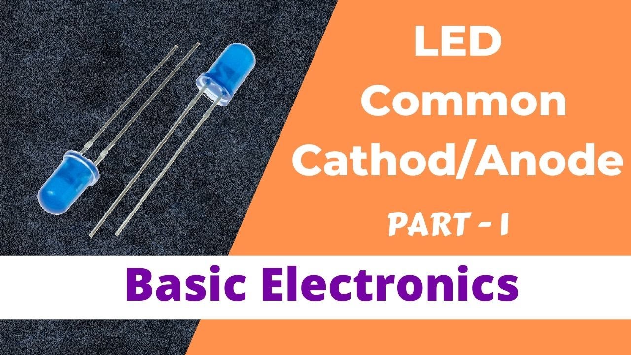
When you dump a bag of fresh components onto your workbench, your first line of defense is visual inspection. Through-hole components are relatively generous with their physical clues. If you are working with classic 5mm or 3mm plastic radial packages, the anode positive lead is almost universally longer than the cathode negative lead. It is simple, intuitive, and practically foolproof out of the tape strip.
What happens when those leads get trimmed for a prototype, or you are working with surface-mount devices? That is where the subtle physical markers come into play. Look closely at the plastic epoxy dome of a standard through-hole component. One side isn't completely round. You will spot a flattened edge molded directly into the base of the plastic casing. That flat side always points directly to the LED cathode notch or negative terminal.
Surface-mount technology flips the script a bit because we do not have long wires hanging off the silicone die. With SMD components like 0805, 0603, or tiny 0402 packages, manufacturers use a physical SMD LED polarity notch on one corner of the ceramic or plastic body. Sometimes it is a subtle bevel; other times, it is a micro-hole cast into the substrate. Look carefully. That physical notch almost always sits on the cathode side.
Flip that tiny SMD component over, and the bottom contacts tell an even clearer story. Most manufacturers print a small green or black structural shape on the underside. You might see a small T-shape, an arrow, or simple green dots. The crossbar of the T or the point of the arrow indicates the direction of conventional current flow, pointing straight toward the negative pad. Miss that detail, and your automated pickup machine will ruin a production run.
- Longer Wire Lead: Indicates the positive anode terminal on un-cut through-hole parts.
- Flat Epoxy Base: Marks the negative cathode side on radial through-hole packages.
- Corner Chamfer/Notch: Identifies the cathode pad on surface-mount ceramic packages.
- Underside Silkscreen Arrow: Points directly toward the cathode pin identification marking on SMD components.
Reading PCB Silk Screen Polarity Markings Without Confusion
Circuit board design software is fantastic, but board designers are human, and human error happens. Reading the white overlay layer—the silkscreen—requires knowing the standard conventions and the occasional weird exceptions. Normally, a proper circuit board LED silk screen polarity layout uses clear geometric shapes to guide your placement.
The classic standard symbol printed on a board is the schematic diode symbol: a triangle pushing against a vertical line. The base of the triangle represents the positive anode terminal, while the bar at the point represents the negative side. Current flows in the direction the triangle points. Easy enough, right? But silk screens are tiny, and full schematic symbols do not always fit on high-density interconnect boards.
When space gets tight, designers resort to abbreviated markings. You will often see a tiny plus sign (+) printed next to one pad, clearly designating the anode. Alternatively, board designers use square versus round solder pads to signal orientation. A time-tested rule of thumb in surface-mount and through-hole layout is that square pads are reserved for pin one or positive anode connections, while standard round pads hold the cathode.
Beware of the inverted notch convention, though. Some engineers draw the silkscreen box outlining the physical package and include a small notched corner on the outline. That outline notch mirrors the physical circuit board LED silk screen polarity indicator on the part itself, which means it points to the cathode. Always double-check your board design files if something looks ambiguous. A quick glance at the CAD layout can save hours of troubleshooting.
- Diode Schematic Symbol: The arrow head points directly at the negative cathode line.
- Plus (+) Sign: Explicitly marks the pad meant for the anode positive lead.
- Square Pad Layout: Frequently designates the positive terminal, leaving round pads for negative.
- Thick Silkscreen Bar: Mirrors the physical bar painted on the negative end of diode components.
Testing LED Polarity: Multimeters and Bench Supplies
Never completely trust a mysterious component pulled from a bargain bin. Visual markers are great, but active testing is the ultimate truth teller when dealing with anode positive or negative LED setup validation. Luckily, verifying polarity on the bench takes less than five seconds if you have a decent digital multimeter handy.
Switch your multimeter dial over to the dedicated Diode Test mode. Do not just use standard resistance measurement; normal continuity modes generally do not output enough voltage to bias the semiconductor junction. In diode mode, the meter pushes a tiny constant current—usually around 1 milliamp to 3 milliamps—across the probes while measuring the voltage drop.
Touch the red probe to one lead and the black probe to the other. If the display shows "OL" or open loop, flip the probes. When the red lead touches the positive anode terminal and the black lead touches the cathode, the diode becomes forward-biased. The meter will show a voltage reading—typically between 1.5V and 3.3V depending on the light color—and the component will faintly glow right on your desk.
If you prefer using a variable bench power supply, proceed with extreme caution. Never connect a light-emitting diode directly to a power source without current limiting. You will instantly destroy the junction. Always place a 1k-ohm resistor in series with your test leads, slowly bring the voltage up to 5V, and check for illumination. If it lights up, the lead tied to the positive side of your supply is your anode.
Look—testing takes an extra moment, but it eliminates guesswork entirely. It is a mandatory step when working with custom ultraviolet, infrared, or high-brightness white units where standard color-coded physical housings do not follow traditional manufacturing rules.
Troubleshooting Common Polarity Pitfalls and Reverse Breakdown Risks
What happens when things go wrong? Installing an LED polarity identification component backward rarely results in dramatic explosions, but it can cause subtle circuit issues. In simple indicator circuits powered by standard 5V logic, a reversed component simply acts as an open circuit. It stays off, blocks current flow, and keeps the rest of the current loop inactive.
However, modern electronics push higher voltages. If your circuit applies a reverse bias voltage that exceeds the component's maximum reverse breakdown rating—which can be as low as 5V for sensitive surface-mount devices—the internal P-N junction collapses. Once breakdown occurs, high current rushes through the chip in reverse, causing rapid thermal runaway and permanently frying the semiconductor structure.
Another classic nightmare is mismatched custom silk screen libraries. Some automated CAD footprint libraries historically drew the component outline with the notch on the anode side instead of the cathode side. If an engineer pulled an unverified footprint into their layout software, an entire automated assembly line might place thousands of components backward. Always cross-reference your component datasheet against the physical layout before ordering stencils.
Fixing a backward component on a populated board requires good technique. Using a standard soldering iron to pry up a multi-pad surface-mount part often tears delicate copper traces right off the FR4 substrate. Reach for a hot air rework station instead. Evenly heat the surrounding area, let the solder liquefy naturally, spin the part 180 degrees with fine tweezers, and let it settle back onto the pads properly.
Seriously, taking a disciplined approach to component placement saves endless headaches down the line. Check the datasheet, verify the physical notch, respect the silkscreen, and measure twice before applying heat.
Common Questions About LED Polarity and Identification
How do I identify anode and cathode on an SMD LED?
Look at the bottom of the component for a printed arrow or T-symbol; the arrow points toward the cathode. On the top casing, look for a chamfered corner, small notch, or green dot, which almost universally marks the negative cathode terminal.
What happens if I wire an LED backward?
In most low-voltage circuits, a reversed component will simply not illuminate because it blocks current flow. However, if the reverse voltage exceeds the component's breakdown threshold (typically around 5V), the internal junction can burn out permanently.
Is the longer pin on an LED positive or negative?
The longer lead on an uncut, through-hole radial package is always the positive anode terminal. The shorter lead indicates the negative cathode side.
How does a multimeter show LED polarity?
Set your multimeter to Diode Test mode. Connect the red probe to one terminal and the black probe to the other. When the red probe is on the anode and the black probe is on the cathode, the component will faintly glow, and the meter will display the forward voltage drop.